
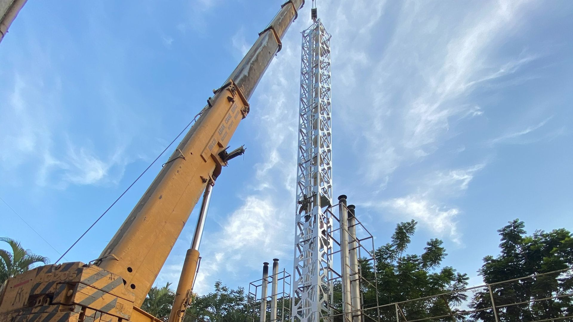
DG exhaust stacks to 30 m — the height the norms demand
Statutory stack height is set by the rule book, not by what is convenient to build. We engineer, fabricate and erect the structure that gets the outlet up there — to 30 metres.
Tallest built
Lattice column, statutory stack height
Reserve Bank of India
Belapur, Kharghar, Nagpur
Steel per column
Legs, bracing, platforms, base plates
How it’s built
The riskiest part of a 30 metre stack is the time people spend at the top of it. Building the column in complete sections at ground level and lifting them whole is what keeps that time short — and it is why the exhaust riser goes in before the steel ever leaves the ground.
- 01
Foundation
Raft, pedestals and tie beams cast on PCC, with holding-down bolts set to the template before the steel arrives.
- 02
Ground fabrication
Two or three complete sections built at ground level — legs, bracing, platform steel and the exhaust riser fitted up the centre.
- 03
Erection
Each section tailed up by mobile crane and landed on the splice below. Work at height is limited to bolting and alignment.
- 04
Connection
Silencer, bellow and the run from the generator tied into the riser, then insulation, cladding and the statutory fittings.
The build, photographed
The fly-through above is a model. These are not — unretouched photographs from our own 30-metre builds: bank premises, bottling plants and factory yards.
-
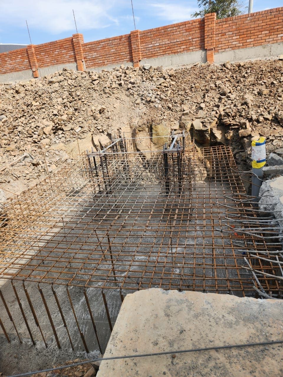
1Foundation — raft reinforcement and the holding-down bolt cage, sized to the soil report and wind zone. -
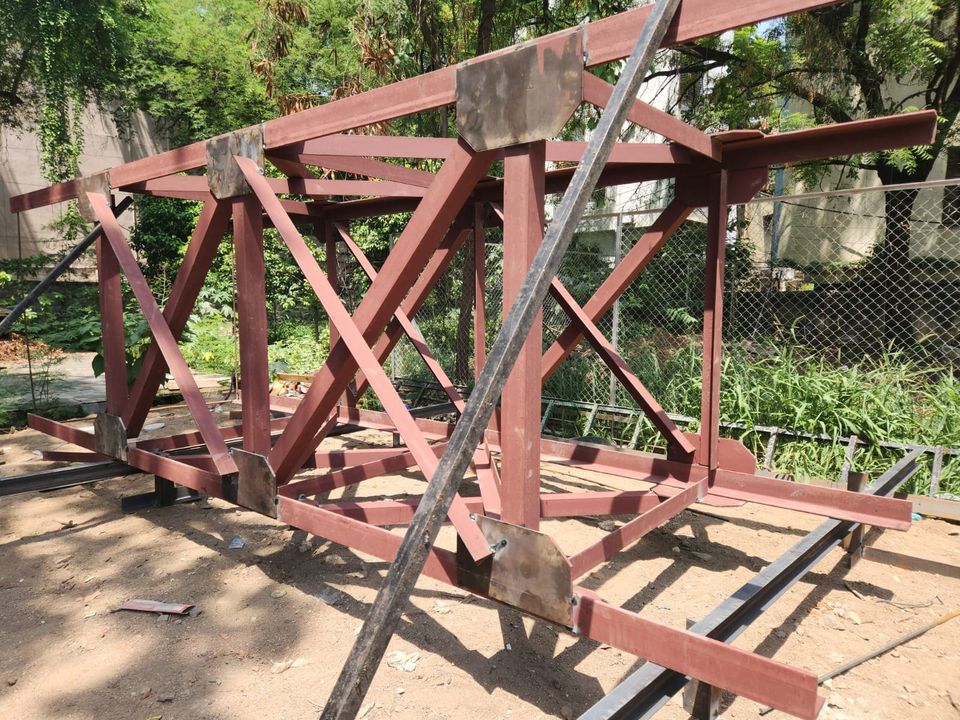
2Fabrication — complete sections built at ground level, flues and platform steel included. -
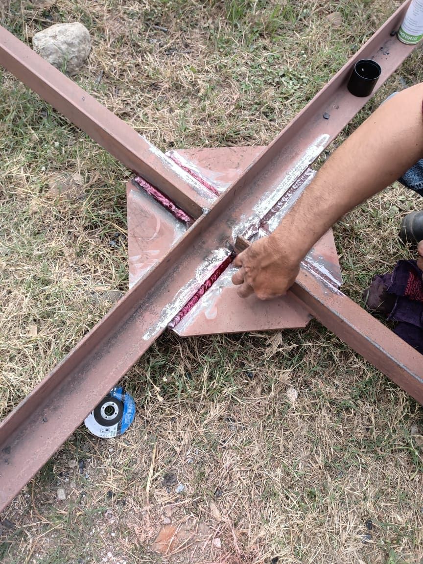
3Weld QA — dye-penetrant testing on gusset joints before anything leaves the ground. -
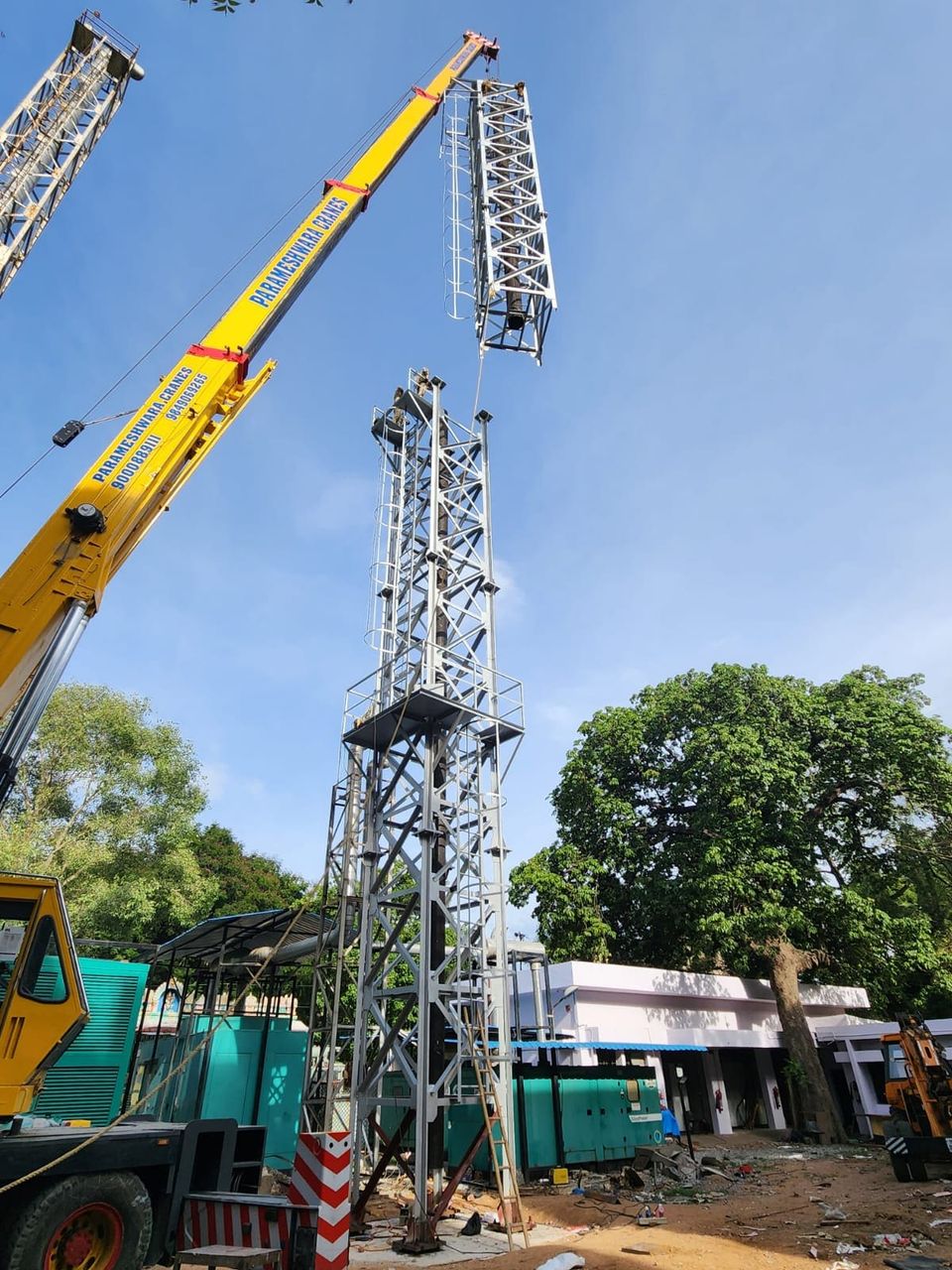
4Erection — each section tailed up and landed on the splice; height work is bolting and alignment. -
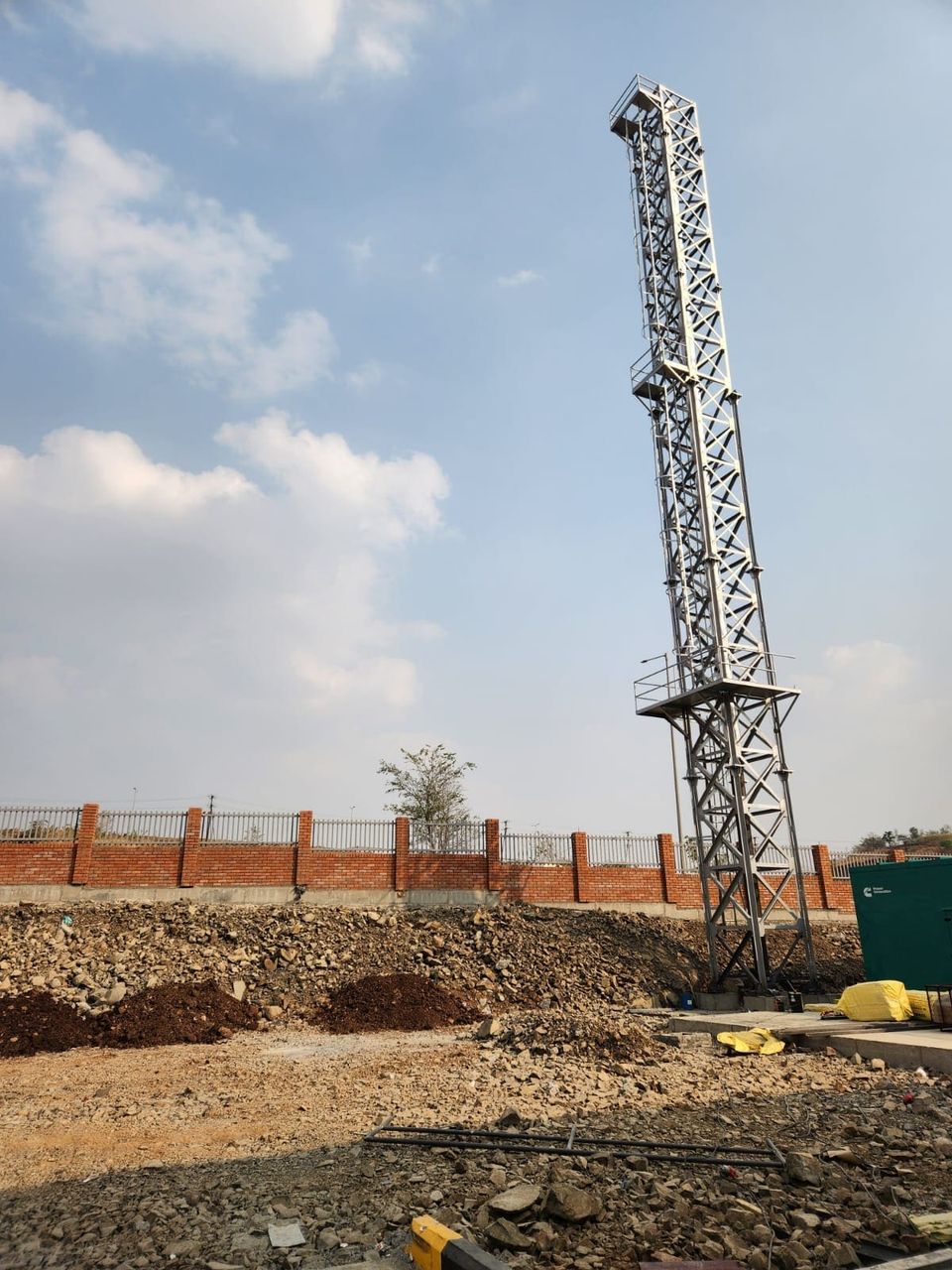
5Complete — ladder, rest platforms, aviation lamp, lightning arrestor and bird mesh, ready for the pollution-check point.
Scope of work
The stack is one line in the BOQ and one owner on site — civil, fabrication, erection and the exhaust run, rather than a structural contractor and a piping contractor pointing at each other.
- Structural design co-ordination and drawing approval
- Foundation: excavation, PCC, reinforcement, raft, pedestals and tie beams
- Shop fabrication of the lattice column, platforms and ladder
- Surface preparation and painting to the specified scheme
- Exhaust piping — MS B-class, insulated and aluminium-clad; twin runs with a fabricated Y-joint on V-engine sets
- Silencers (two on twin-bank sets), steel bellows, hangers and support steel
- Crane erection in ground-fabricated sections, splice bolting and alignment
- Aviation lamp, lightning arrestor, bird mesh, pollution check point
Typical engineering
Indicative of the columns we have built. Every job is confirmed against its own soil report, wind zone and set rating before fabrication — these are the shapes those checks usually land on.
| Column | 1500 × 1500 mm four-leg lattice, 30 050 mm assembled |
|---|---|
| Legs | ISA 150 × 150 × 15 to ~18 m, ISA 110 × 110 × 12 above, spliced in ~6 m lengths |
| Bracing | ISA 65 × 65 × 8 |
| Base | 400 × 400 × 36 mm base plates on 700 × 700 pedestals |
| Foundation | 5000 × 5000 × 700 mm raft, 300 × 600 tie beams, on PCC blinding |
| Riser | Suitable to the DG set MS Class B ERW pipe, insulation, aluminium cladding through the centre of stack |
| Twin-bank sets | V-engine sets (≈1000 kVA up): two runs, two silencers, fabricated Y-joint; common pipe 14 in (1000 kVA) to 18 in (2000 kVA), MS B-class ERW, insulated and clad |
| Access | Platforms at 7.5, 21 and 30 m; caged ladder full height |
| Fittings | Aviation lamp, lightning arrestor, bird mesh, pollution check point, ash collection point |
Frequently asked questions
How is a 30 metre stack actually erected?
Not panel by panel in the air. The column is fabricated on the ground in two or three sections, each one complete with its bracing, platform steel and the exhaust riser already fitted up the centre. A mobile crane then tails each section up and lands it on the splices. Working at height is reduced to bolting the splice joints and the final alignment.
What steel goes into the column?
A 1500 × 1500 mm four-leg lattice. Legs step from ISA 150 × 150 × 15 at the base to ISA 110 × 110 × 12 above roughly 18 m, spliced in about 6 m lengths, with ISA 65 × 65 × 8 bracing throughout. A typical 30 m column works out near 10.4 tonnes before platforms and handrail.
What is the foundation?
For a 30 m column, an isolated raft around 5000 × 5000 × 700 mm with 700 × 700 pedestals and 300 × 600 tie beams, cast on a PCC blinding. Final sizes are always confirmed against the soil report and the wind zone — the numbers above are what these columns have typically needed, not a substitute for design.
Does the exhaust pipe go inside the structure?
Yes. The pipe — sized to suit the DG set, with insulation and aluminium cladding — runs up the centre of the lattice, guided off the legs at intervals. It is installed during ground fabrication so it stands up with the steel, rather than being threaded through afterwards.
How do you decide the stack height?
By the CPCB/MoEF rule for the set rating, not by preference — which is why the height is a compliance input to the structure, not an afterthought. Our stack height calculator works it out for a given kVA, and the structure is then engineered to whatever that height demands.
What else is fitted at the top?
Access platforms with grating and handrail, a caged ladder the full height, aviation obstruction lamp, lightning arrestor, bird mesh at the outlet, a pollution check point for sampling, and an ash collection point at the base of the riser.
Why do large DG sets have two exhaust pipes?
Because the engine does. Generator sets from about 1000 kVA upwards run V-configuration engines with two turbochargers — so two exhaust lines leave the set, each through its own silencer. After the silencers a fabricated Y-joint merges them into one common pipe, and that single run continues to the stack riser. The common pipe is sized to the rating — 14 inch at 1000 kVA rising to 18 inch at 2000 kVA, in MS B-class ERW — and the whole run is insulated and aluminium-clad for heat protection.
Can several DG sets share one stack?
No — and this is a different question from one set’s two banks meeting in a Y, which is standard. Manifolding separate sets into a common exhaust lets condensate and exhaust gas migrate into whichever engine is standing idle, with no failsafe once they are joined. Each set gets its own riser. Where a site regulation forces a single chimney, it becomes an engineered special: per-set condensate drains, duct entries angled into the stack, minimum spacing between nozzles, and the stack bore sized for every set running at once.
What stops rain and condensate getting into the engine?
Four details, all standard on our stacks: a rain cap and bird mesh at the outlet, horizontal pipe runs sloped away from the engine, a condensate drain after the silencer, and thermal-expansion bellows anchored so pipework forces never reach the turbocharger. During erection, every open engine and pipe end stays blanked until the exhaust system is complete — rainwater in a stopped engine is how hydrolock and seized turbos happen.
Where we work and who we serve
Reply within 4 working hours. Engineered offer within 24 hours.